The voltage on this pin represents the mechanical angular speed in rads. A state feedback gain matrix is designed for the dc motor with the help of pole-placement technique.
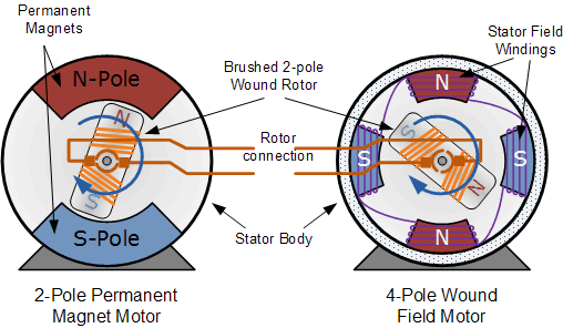
What Are Wound Field Motors And Where Are They Applied
In an alternating current AC motor a magnetic field changes polarity on its own.
. The coils cut the magnetic lines of forces to induce an EMF. In the parallel-connected-system all generators and motors are arranged in parallel. Practical dc machines have air gaps ranging from 05 mm to 15 mm.
The separately-excited machine has no physical connection between the field and armature windings. Describe the procedure for design of field system of DC machine. The number of turns.
The direction of this current in DC generators can be observed through the rule of Flemings Right-hand. The rotor construction of the turbo alternator is as shown in fig. In a DC generator when the coil placed in the magnetic field is rotated by means of a prime mover or any handle.
Design of Commutator Brushes. BE - ELECTRICAL ENGINEERINGSubject. These various parts of DC Generator are described below in detail.
Describe the procedure for design of interpoles of DC machine. A DC motor has some significant advantages and one of them is the simplicity of its control system. Design of the field System.
Machine a torque angle of 90 is the normal condition with field and armature mmfs maintained in quadrature by the angular-position switching action of brushes and commutator. In stator of dc machine there is a frame that provides protection and support to internal structure from external environment in this frame there are poles that produce field at the stator. Separately-excited shunt-connected series-connected and compound.
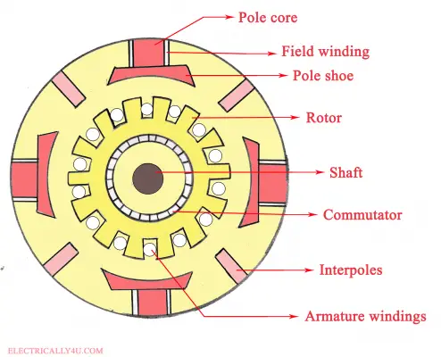
Normally 70 of the rotor is slotted and remaining portion is unslotted in order to form the pole. The materials used for this are cast steel cast iron otherwise pole core. DC motors are described by the method used to excite the field.
A practical DC machine also needs a commutator brushes poles and bearings. Because of the parallel connection full voltage is applied to the field winding. The design is influenced by numerous factors such as MMF per pole flux density the resis.
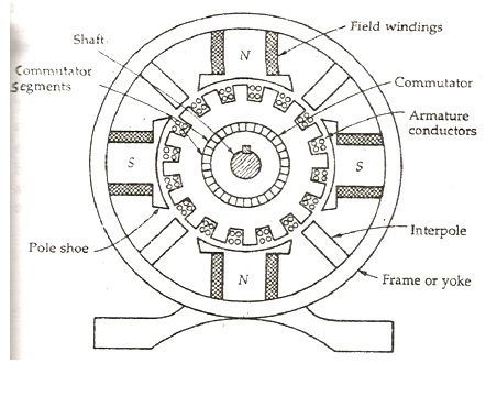
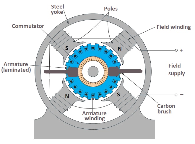
Systems the generators and motors are all connected in series in one circuit. The magnetic field system consists of Mainframe or Yoke Pole core and Pole shoes and Field or Exciting coils. Magnetic Frame and Yoke.
Flux produced by field coils emerges from N pole and cross the air gap to enter the armature tooth. A DC machine is made out of two essential parts one stationary and one moving called the field and the armature. The modular design of the training system allows for applications which go above and beyond the.
In addition to these permanent-magnet and brushless types are also available normally. Design of Field Poles Field Coils. In case of turbo alternators the rotor windings or the field windings are distributed in the rotor slots.
Positive and negative terminals of armature winding. Each circuit is excited from its own power supply. Of field coils is required to set up flux in the air gap.
Of dc motor using state space approach. Magnetic circuit of dc machine comprises of yoke poles airgap armature teeth and armature core. This induced Emf develops current in the armature winding.
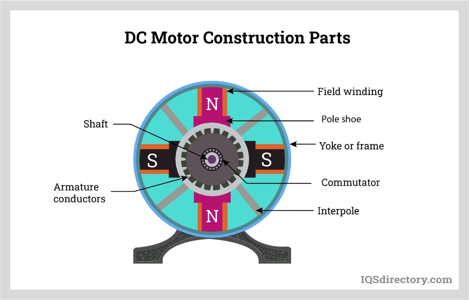
The field winding of DC motor are made with field coils copper wire wound over the slots of the pole shoes in such a manner that when field current flows through it then adjacent poles have opposite polarity are produced. It produces the main magnetic flux. This component models a brushed DC machine where the field is set by an energized field winding.
An essential example of a DC machine is a copper coil spinning on its own axis between two magnets. Field system Since armature and field systems are composed of materials that have high permeability most of the mmf. The current flow through the field winding is very small.
Therefore shunt winding is designed with a large number of turns with high resistance. Basic principles of the DC shunt motor _____ 5. The pole of the DC machine is an electromagnet and the field winding is winding among pole.
By reducing the length of the air gap we can reduce the size of field coils ie. 1- Field magnetic poles 2- Armature 3- Commutator. The four most common methods are.
In this type of DC machine the field winding is connected in parallel with the armature winding. Basic principles of 3-phase machines In the field of drive technology DC drives currently play a major role in mobile drive solutions. Find the main dimensions of the machine if it has to.
Dhruvang R Gayakwad Assistant Professor 26 A. The common feature and the essential condition of all DC motors is the generation of a variable magnetic field that provides their non-stop operation. It can be built with the annealed steel laminations for reducing the power drop because of the eddy currents.
You can attach mechanical loads sensors or motion controllers to the motor through this pin. Program to Design a series connected DC machine Number of conductors per parallel path 110 Hence mean emf induced per conductor 41818 Average Flux density Bav 06847 Diameter D of the other machine 07620 Length L of the other machine 02793 Number of conductors per parallel path 90. The part of pole that is close to rotor distributes the flux on the surface of the rotor is known as pole shoes.
Wound-field dc motors are usually classified by shunt-wound series-wound and compound-wound. The field winding basically form an electromagnet that produces field flux within which the rotor armature of the DC motor. 2160912 - Design of DC Machines and Transformer Sem-6Created By.
This video deals with the design of field systems in DC machines. A 5 kW 400 V 4 pole 1500 rpm DC shunt generator has the average flux density in the airgap as 12 Wbm 2 and the specific electric loading is 21000 Am. Overview of direct current machines _____ 3 Exercise 1.
Whenever field winding is energized then the pole gives magnetic flux. In both cases the speed and direction of rotation of the motors is changed by varying the generator and motor excitations as shown in Figure 4612. The path of magnetic flux is called magnetic circuit.
Magnetic Field System of DC Generator The Magnetic Field System is the stationary or fixed part of the machine. The performance of dc motor under various conditions is simulated using MATLABSIMULINK environment and simulation result demonstrates the feasibility of the proposed system. Electrical Machines and Drives Third Edition 1996.
Construction Of A Dc Generator Explanation Of Its Various Parts Circuit Globe

Construction Of Dc Machine Generator Motor
Construction Of Dc Generator
Dc Motor What Is It How Does It Work Types Uses

Construction Of Dc Machine Electrical Wiring Colours Diagram Electrical Installation

Construction Of Dc Motor Parts Images Electrical4u
Construction Of Dc Motor Your Electrical Guide

A Dc Motor Is An Electrical Machine And Operates On The Principle Whenever A Current Carrying Conductor Magnetic Field Mechanical Force Electricity Magnetism
0 comments
Post a Comment